This is the presentation that I contributed to the GDC 2001. In here, I describe a 3D rendering technique for implementing volumetric fog.
If you want to compile and run the source code, you'll need the data files, which are included with the demo executable. Just uncompress the ZIP file in the same directory as the source files.
Nowadays, in the 3D-programming world, everybody is talking about multi-texturing and all the cool things you can use it for. But there are many different multi-texturing techniques that already require all the texture processing power in an accelerator, or even more. And besides, traditionally, the main reason for using a texture in 3D rendering is that you can add a lot of detail in one fell swoop.
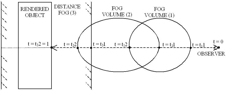
Fog, on the other hand, is usually a very low-resolution effect. Its main use so far is what's called "distance-fog", which is the use of fog to smoothly eliminate excess geometry that's a certain distance from the point of view, and to prevent popping as new geometry gets close enough to become visible. But fog can also be used to enhance the atmosphere and realism of a game or 3D scene. The techniques used to do that are usually called "volumetric fog techniques".
What this class focuses on is how not to use those precious texture units for implementing different volumetric fog techniques. Instead, it is based on the premise that the geometry will be "dense enough" to avoid any major visible artifacts. "Dense enough" will have to be defined and adjusted by the engineer when he or she is using these techniques.
In order to use vertex-interpolated volumetric fog effectively, there's a missing feature in today's consumer-level graphics hardware, and that is the ability to specify a fog color that changes throughout a mesh. To illustrate this, imagine an underwater scene where you use volumetric fog to darken the entrance into a cave. The normal, distance fog should be blue or green for the water, while the volumetric fog for the cave should be black. Now imagine, within that scene, a long eel emerging from the cave. The far end of the tail should be completely fogged in black, while the head should be fogged normally with the blue-green underwater distance fog.
The method I propose to overcome this limitation is a little abuse of the specular and diffuse components present in all of today's graphics hardware. So, here's how those components are commonly used:
Fragment = texture * diffuse + specular
where Fragment represents the resulting color for a rendered pixel, texture is the surface's color normally read from a texture, diffuse is the interpolated diffuse color and specular is the interpolated specular color. All colors range from zero (black) to one (white), and the formulas are applied to all the components (red, green and blue) independently.
Now, what we really want is something like:
Fragment = texture * diffuse * fog + specular * fog + fogColor * (1 - fog)
where fog is the interpolated fog intensity, and fogColor is the interpolated fog color. Values for fog range from zero (fully covered by the fog) to one (not covered by the fog). The trick consists in reorganizing the math in this manner:
Fragment = texture * diffuse * fog + specular * fog + fogColor * (1 - fog)
So, if we make:
newDiffuse = diffuse * fog
newSpecular = specular * fog + fogColor * (1 - fog)
now we have again:
Fragment = texture * newDiffuse + newSpecular
which is the original formula supported by all current graphics hardware.
There is only one problem with this method: the hardware will interpolate the newDiffuse and newSpecular values linearly, which means that neither one of the original interpolated values that we wanted (diffuse, specular, fog and fogColor) will interpolate linearly. This causes the polygons to have different pixel colors inside than if we had had independent interpolators. The visual results are not bad, anyway, and can be lessened by careful use of finer meshes.
This technique is not only useful to render volumetric fog. It can also be used to render special effects without requiring additional geometry. Among others, you can have fog gradients (very useful in underwater environments and sunsets) and directional fog colors cues, like nuclear explosions in the far distance.
The most common implementation of fog in 3D graphics is what's called linear fog. Mathematically, linear fog is a very simple concept:
take two distances from the observer, which we will call minFog and maxFog. minFog is the distance beyond which fog happened,
and maxFog is the distance where the fog becomes solid, as illustrated in Figure 1. So,
calculating a fog interpolator value is easy:
fog = 1 - clamp01( (camDistance-minFog) / (maxFog-minFog) )
where camDistance is the distance from the observer (the camera) to the point that is being fogged, and clamp01(x) equals x
if x is between 0 and 1, 0 if x is less than 0 and 1 if x is greater than 1.
For calculating volumetric fog, though, using fogMax and fogMin doesn't make that much sense, so we will be using a slightly different expression for this formula:
fog = 1 - clamp01( distance * fogDensity )
where distance is the distance that the light must travel through a volume of fog (see Figure 2),
and fogDensity = 1/(maxFog-minFog) is the fog density, which is a value that we will define in general as
"one over the distance above which the fog covers everything completely". Distance = camDistance-minFog for normal, distance fog.
In order to have volumetric fog, we'll need to somehow define the volumes of space where the fog will be confined. There are many different volumes to choose from, but in this talk we will concentrate on three basic volumes that are simple but very powerful: the half-space, the sphere and the ellipsoid, and also in the classic distance fog. Other volumes (cylinders, cones, convex hulls, etc…) can easily be used, provided that we research the appropriate math.
We will be measuring the distance that a ray of light traverses the different fog volumes, so we will concentrate in the mathematical formulas for the intersection between a ray and the volumes. We will define the ray of light in reverse: originating at the observer point (O) and extending in the direction of the geometry being rendered (D). We will use the parametric formula of a straight line:
X = O + D * t
Where X is a point on the line and t is the parameter, which is 0 at the observer and 1 at the object being rendered. The value of the parameter t for the intersection points is the result we will want. We will assume that any volumes used are non concave, so that only one segment of the ray will traverse through each of them. We will call t1 to the parameter for the point where the ray enters the fog volume and t2 to the parameter for the point where the ray exits. Note that the values calculated can be outside of the range (0, 1), in which case they will be clamped to that range later on in the actual algorithm.
The points of t1 and t2 are easily calculated from minFog and maxFog as:
t1 = minFog / magnitude(D)
t2 = maxFog / magnitude(D)
See Figure 1 for reference.
In 3D, an infinite plane divides the space into two half-spaces. The half space is defined mathematically by a vector normal to the plane (N)
and a point contained in the plane (P). Its general formula is:
(X – P) * N > 0
Therefore, its intersection with the ray of light is (see Figure 3):
t > ((P–O)·N) / (D·N) (if D · N > 0)
t < ((P–O)·N) / (D·N) (if D · N < 0)
So the half-plane of fog will extend towards infinity in the view direction in the first case, and backwards behind the observer in the second case.
In the fog calculations, we will be using two points, which we will call t1 and t2, which represent respectively the point of entry
into the fog and the point of exit. Therefore, we will want to make t1 = t and t2 = infinity, or t1 = -infinity and t2 = t,
as appropriate depending on the sign of D·N.
If D·N is 0, then the ray doesn’t intersect the volume boundary. In this case, if (P–O)·N<0, then the whole ray is inside of the volume,
while if (P–O)·N>0, then the ray is outside of the volume.
A sphere in a 3D space is mathematically defined as its center point (C) and its radius (r). Its general formula is:
(X – C)2 < r2
Therefore, its intersections with the ray of light is (see Figure 4):
t1 = {-(O–C)·D - sqrt( [(O–C)·D]2 - D2*[(O-C)2 - r2] )} / D2
t2 = {-(O–C)·D + sqrt( [(O–C)·D]2 - D2*[(O-C)2 - r2] )} / D2
These formulas will always result in t1 <= t2, so the sphere of fog will lie between t1 and t2.
If [(O–C)·D]2-D2·[(O-C)2-R2] is less than or equal to 0,
then the ray doesn’t intersect the volume.
Both the half-plane and the sphere are simple volumes that can be manipulated analytically without problem.
But the ellipsoid is more complicated, so we will use a little trick that simplifies the calculations significantly.
An ellipsoid can be seen as a unit sphere that has been scaled, stretched, rotated and translated in space.
Now, scale, stretch, rotation and translation are all linear transformations that can be specified and manipulated using 4x4 matrices.
The key here is that the resulting 4x4 matrix defines a linear transformation that is reversible,
so we can always compute the inverse matrix (E), which can be used to transform the ray into the space where the ellipsoid becomes the unit sphere.
Not only that, the t1 and t2 values calculated in that space are valid also in the world or camera spaces, where the ray was defined.
Transforming the ray is easy. It consists on transforming O and D into two new vectors Oe and De:
Oe = O * E
De = D * E
So then we can use the formulas we calculated previously for the sphere, only this time we know that C = 0 and r = 1:
t1 = {-De·Oe - sqrt( (Oe·De)2 - De2*(Oe2 – 1) )} / De2
t2 = {-De·Oe + sqrt( (Oe·De)2 - De2*(Oe2 – 1) )} / De2
Again, we know that t1 <= t2, so the ellipsoid of fog will lie between t1 and t2.
Also, if (Oe·De)2 - De2*(Oe2 – 1) is less than or equal to 0,
then the ray doesn’t intersect the volume.
The half-space
The sphere
The ellipsoid
We will distinguish three possible implementations, ranging in difficulty: when there is only one fog volume, when there are several separate fog volumes, and when there are several interpenetrating fog volumes.
If we make a scene where there is a fog volume, defined by its volume (which we use to calculate t1 and t2), density (volFogDensity) and color (volFogColor), the technique for rendering is quite obvious:
Now, the problem comes when trying to mix different types of fog, or more than one fog volume. In this case, we will have to sort all the (t1, t2) ranges for the different fog volumes, and apply them in front-to-back order:
Sorting front-to-back allows us to have an early exit in case a volume completely fogs out what it has behind.
The formulas from points 4 and 5 come from applying the normal fog formula to the new fog volume:
Result = color*fog + fogColor*(1–fog)
and adding the fog coefficients:
fog = 1 – [ (1 – fog) + (1 - fog) ]
to ensure that the fog stays linear with the distance across the different volumes.
The most complex setup happens when two fog volumes share a portion of the range between the observer and the object being rendered.
In Figure 6 we see what’s probably the most common case where interpenetrating happens:
a fog volume that is inside of the distance fog. In this case, there’s no way to properly sort the two distinct volumes.
It’s not possible to assert that the volume is "behind" or "in front of" the distance fog.
Intuitively, in this case the solution lies in sorting three ranges (t21,t11), (t11,t12) and (t12,t21),
which can indeed be sorted without problems. For the first and third ranges, the color and density values are taken from the distance fog,
but for the range where the fogs get mixed, we will have to properly mix the values for both fogs.
A very intuitive way to mix them, which is the one I’ve used, is by calculating the color of the mix using a weighted average on the relative densities.
So, if volume 1 has twice as much density as volume 2, then the resulting color should be (2*vol1FogColor + vol2FogColor) / 3.
This is achieved with the formulas:
mixFogDensity = vol1FogDensity + vol2FogDensity
mixFogColor = (vol1FogDensity*vol1FogColor+vol2FogDensity*vol2FogColor) / (vol1FogDensity + vol2FogDensity)
Of course, the thing can become pretty complicated really quickly, as shown in Figure 7.
So, how can we generalize this to many volumes?
The algorithm I found makes this task pretty easy and fast. It consists in having an array of (t, fogColor, fogDensity) tuples,
and filling it in with proper values for the entry and exit points of the visibility ray into the different fog volumes:
The sorting can be done very fast because the list is always likely to be already sorted. A bubble sort will do very nicely.
The distance fog values are the ones that can easily be out of order, so it’s best to add them after the list has been sorted, using insertion sort.
Implementation details will be discussed in the lecture during the GDC. Also, demos will be shown, demonstrating the different features and problems that this technique presents, and a short study on how some of this could be implemented using DirectX 8 vertex shaders.
Also, alternative math formulas and adjustments will be discussed, with the aim of improving the visual quality and reducing the impact of visual artifacts.
All demos, slides and additional material will be put available for download after the conference.
The volumetric fog technique presented is an interesting application of the concepts of ray casting, renderer interpolators and 3D geometry math, and the range of effects that can be achieved is very encouraging.
Nevertheless, the technique isn’t free of problems. The most important, visually, is that small fog volumes can reveal the polygon mesh layout along their edges. In order to avoid this, the fog volumes must be sensibly larger than the polygons rendered. Also, computationally, this technique puts a heavy strain on the vertex processing pipeline. This can make it unsuitable for some purposes.
In any case, the technique is proven (it was used in the Ripcord Games title "Armor Command") and definitely worth studying in detail.
All trademarked things I mention here are TM by their respective owners. If you are one of those owners and want to be specifically mentioned, please, contact me and I'll include it.
Go back to the main index of JCAB's Rumblings
Wow!
hits and increasing...
To contact JCAB: jcab@JCABs-Rumblings.com
Last updated: Wednesday, 14-Nov-2001 23:37:48 PST